Client: LXT AI Inc

This is a summary of the tasks that have been performed and executed for the previously mentioned customer. 5 cameras were installed on 1 floor and 6 cables were pulled around the office.

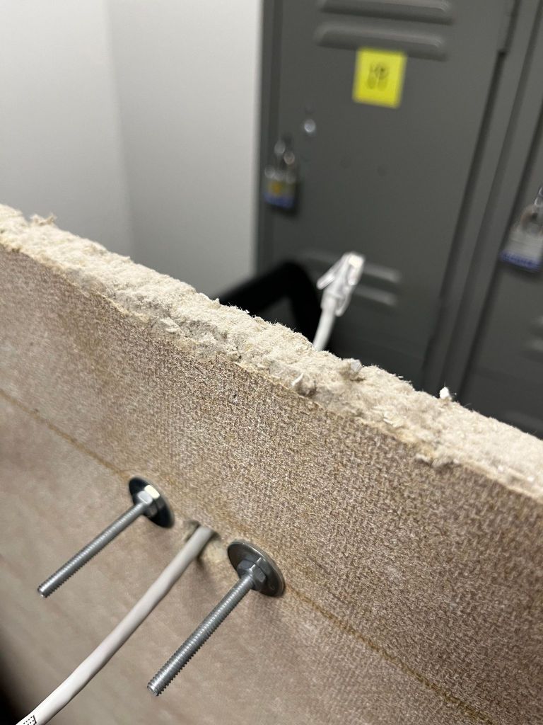
  • Route the CAT5e patch cable through the hanging ceiling and terminate the RJ-45 end following T568A standard

  • Use a washer and a nut to secure the bullet camera to the ceiling tile, without damaging the asthetics

Snort open-source IDS (Intrusion detection system) Install Ubuntu 22.04

Required

  • 1 Local area network
  • 2 hosts one running Kali Linux (attacker) and one running Ubuntu 22.04(Snort IDS)
  • TCP/IP communication between hosts needs to be established before-hand
  • Clock and Date settings must be configured correctly

TCP/IP addressing table

Subnet nameIPv4 range
Virtual Network 2 (Vmnet2)192.168.200.0/24
NodeIPv4 Address
Kali Linux , the attackereth0 LAN 192.168.200.145/24
UbuntuServer, Snort IDSens33 LAN 192.168.200.148/24

Snort installation and analysis

  • From UbuntuServer open a Terminal window
    1. Type sudo su –
    2. Type apt install -y snort*
    1. Type systemctl restart snort , no error should happen
    2. Type systemctl status snort, must be active
    3. Type snort -D -A -i ens33 -c /etc/snort/snort.conf
  • Here are the following options explained
    1. -D , runs the IDS in daemon, it frees the terminal , you can close it without interrupting your analysis
    2. -A snort runs in alert mode
    3. -i sniff packets on this interface
    4. -c config file location

XMAS attack analysis

  • From Kali open a Terminal window
    1. Type sudo su –
    2. Type nmap -sX 192.168.200.148
  • -sX is a XMAS scan technique
  • From UbuntuServer, open a Terminal
    1. Type tail -f 10 /var/log/snort/snort.alert.fast
    2. You can clearly see the discovery of the XMAS attack on the Snort Intrusion Detection System

Configuration of Azure Application GW Load-Balancing

Required

  • 1 virtual networks
  • 1 Scale Set
  • 2 subnets
  • HTTP server running on both VMs

TCP/IP addressing table

Subnet nameIPv4 range
BLUEVNET Virtual Machines subnet range172.16.100.0/24
BLUEVNET Application Gateway subnet range172.16.200.0/24
NodeIPv4 Address
WEB-SERVER 0LAN 172.16.100.4/24
WAN 52.235.20.35
WEB-SERVER 1LAN 172.16.100.5/24
WAN 20.220.68.16
APPGWLAN 172.16.200.10/24
WAN 52.229.110.179
  • Create the APP. GW. from the portal.azure.com
    1. Search for Application Gateways and select Create
    2. On the Basics page configure the following info , and hit Next ;
      • Subscription
      • Ressource group
      • Virtual Network
      • Subnet
    3. On the Frontend page configure the following info, and hit Next
      • Frontend IP address type
      • Public IP address
      • Select Yes on Use a private IP address
      • Input the application gateway static Virtual Network IP address
    4. On the Backend page click Add backend pool and configure the following info and hit Next
      • Name
      • Add VMSS Select your VMSS target
    5. Click on the Add routing rule plus sign and configure the following info and hit Next
      • On the Listener page configure the following info
        • Name
        • Listener Name
        • Frontend IP
        • Protocol
        • Port
        • Listener Type
        • Error page url
        • Single Site
        • No URL path-based routing
      • On the Backend targets page configure the following info
        • Backend type pool
        • Backend target click on Add New under Backend Setting
          • Name your backend settings and leave defaults click Add
  • Review and create

You can now access both web servers from the Application Gateway Public URL. Try turning off one of them and see ! By default it uses round-robin when both are running.

Configuration of Azure Virtual Network Peering

Required

  • 2 virtual networks
  • 2 virtual machines in each subnets

TCP/IP addressing table

BLUEVNET subnet range172.16.100.0/24
REDVNET subnet range192.168.100.0/24
BLUEVNET-SERVER172.16.100.4/24
REDVNET-SERVER192.168.100.4/24
  • Create the peering from the portal.azure.com
    1. From Virtual Network select BLUEVNET
    2. From the menu select Peering and click Add
  • Configure the connection
    1. Input Peer Link Name BLUEVNET_2_REDVNET on this virtual network
    2. Leave the defaults traffic rules
    3. Input Input Peer Link Name BLUEVNET_2_REDVNET on remote virtual network
    4. Select the remote virtual network REDVNET
    5. Leave the defaults traffic rules and click Add
  • Peering is configured